

This was a project which I did during my college days. At that time I used MATLAB for programming and an Atmega based development board for the control. Anyway now as I am learning programming in more depth and came across a new language called Julia , which is a really great open source alternative for MATLAB. In fact I felt it was quite better than MATLAB in some aspects. I will explain why I felt that at the end of this post.
The real inspiration for this project was google chrome labs' Sketchbots. The thing is sketching robotic arm is a very simple example to show the ability of a robotic arm to perform sophisticated tasks. For all the robotic arms the greatest deal was to move it to a desired position. I thought it could be a first step to many other projects, say 3D printers, PCB drilling machines( I hated it when we had to hand drill our PCBs), an automated welding mechanism, and may be a CNC type cutter.
You can find all the documents related to this project in my github repo below
https://github.com/RitwikGopi/roboticarm
And for a detailed technical side you can refer my project report if you like.
https://github.com/RitwikGopi/roboticarm/blob/master/final%20report.pdf
The idea is simple. You feed an image that you want to draw to a program, and your arm should draw it. I will explain shortly how I achieved it step by step. First thing I needed to do was to select what kind of arm to build and create a mathematical model. For this specific purpose an arm with a 2 degree of freedom of motion was enough. So my arm basically has 2 points in which it has rotatory motion and 2 linkages. And rotating angles were limited to 180 degree( mainly because common servos have 180 degree motion and also to make a resemblance to human arm).
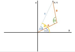
Above picture shows a basic model of arm I designed. And using kinematic equations( more like basic trigonometric equations and stuff) we will calculate the drawing area of arm. That means if angles made by linkages of arm are known we can find the point at which arm has reached by calculating x and y co-ordinates. So if we can find all the points for combination of all angles possible by 2 linkages we can find the total drawing area. To find this I wrote a code.
https://github.com/RitwikGopi/roboticarm/blob/master/drawing_area.jl
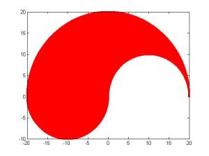
It is a function with arguments as length of linkages of arm. So if you call this function in Julia with lengths of linkages it will plot the total area where your arm can draw. A sample plot with arm lengths as 10,10
Our next task is to select a suitable area. I selected a rectangular are with x-axis from -16 to -4 and y-axis from -6 to 8. And I built the arm with 2 servos and other available things.
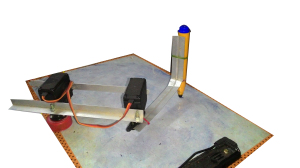
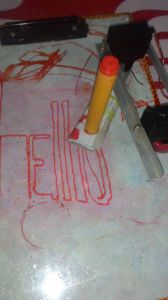
Yep that's my arm. Not what you expected right? I really didn't have a lot of facilities or money, so had to make it with what I had. Okay let's get going. So after selecting a drawing area, I calculated angles needed by servo to reach all the points in the drawing area using inverse-kinematics. I stored those values in two 2D arrays, so that I could use that as a look up table.(You can refer my project report for a detailed explanation on this)
My next step was to load the image. There is a straight forward function to open the image "imread(filename)". Anyway for further processing I needed to convert the image to black and white(not grey scale, in BW format 0 represents black and 1 represents white). I used a built-in function for that in MATLAB, anyway I couldn't find one in julia. So I did a trick to get around it. I drew image using a single basic color(red in my case) and then after loading image I extracted array representing blue color( I could have used green as well). So I will get an array similar to black and white of the image.
Next step was to calculate the angles required to draw points present in the image. First I thought of doing a row by row search and drawing the image. But it would be then more like a plotting robotic arm rather than a sketching robotic arm ( also i don't have a 3rd servo to move the pen up and down). So I formulated a new algorithm. First it would search for a point by row, then once it finds a point it will search it's adjacent pixels for a point. This step is continued recursively using a function to find a continues line.
https://github.com/RitwikGopi/roboticarm/blob/master/check.jl
This is where I found Julia better than MATLAB. In MATLAB main problem I faced was that the recursion depth of MATLAB was around 500. So if there were more than 500 continues points program will crash. So I had to make exit the function once it reached 500 continues points and start over again. But in case of julia I didn't face such a problem. I was able to check around 2000 continues points and the program was working fine. In fact it was enough for most cases. In this function it will store the angles needed to draw those points in order in an array.
Then in the next step I calculated pwm values needed to be generated for 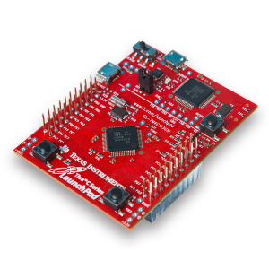 controlling the servos. The servo control was done using Tiva C Series TM4C123G LaunchPad. I used uart communication to send the pwm values to micro-controller and then generated pwm using those values. So that way my arm could draw the image :)
I used the above function for the purpose of sending pwm values. I will read pwm values from each array for servos and send it one by one.